Written up by forum member 7t2vette
Okay, now that the home pages are back up,I can post some pics on this subject. I will explain to you how I did this on my 72, which did not come from the factory with this option. I am not sure what year this was an option, but I would guess 78 or 79 was the first. Wether or not you can copy what I did on those years and newer, I don't know because I am unfamiliar with the factory set up. If the factory used a two-wire actuator, then you should be able to substitute an aftermarket actuator for the factory piece with a little fabricating perhaps, and it should work provided that the rest of the factory system (relays,circuit breakers,ect...) is in working order. This install is completely hidden for those NCRS types that want to do this-you know who you are *cough* Juliet *cough*
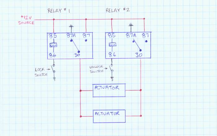
My system is controlled by an aftermarket alarm. The numbers on the wiring diagram inside the relays represents the terminal numbers on the relay. This wiring can be changed to operate any other way you like. My alarm operates the switches I have indicated attached to terminal 86 on both relays. Those "switches" are actually ground output signals from the alarm. If you don't have an alarm, or want to control the locks manually, you will need to install two switches, one for lock, one for unlock, with one side of the switch going to ground as shown in the diagram, and the other side going to terminal 86 of the appropriate relay(lock or unlock). This will operate BOTH doors at once. If you want individual control, then you will have to have a set of switches and relays for each door, for a total of 4 switches and 4 relays.
Electrically speaking, here is how it works: if you look at the diagram, you will see that in it's current state, both coils are open (have no ground input) and both sides of the actuators are grounded. The actuators move in one direction when + and - 12v are applied to the wires, and they move in the opposite direction when + and -12v are reversed. There is no set direction to install them, but you have to get the wiring right to make them move in the right direction when you want to lock or unlock the doors.
When either coil gets a ground signal on terminal 86, it causes the coil to move the internal switch from terminal 87A to terminal 87 which completes the circuit and sends +12v to one side of the actuators (which side depends on which relay coil you just energized). The other side of the actuators is still connected to ground via terminal 30,through the internal switch to terminal 87A ,which is grounded. The actuators move the opposite way when the other coil receives a ground signal on terminal 86.
The actuators can be bought at any good car stereo/alarm store for under$10. The relays can be bought there too or at a car parts place (usually near the fog lights section) for around $5 each. This is an inexpensive project to do, and it is cool too! I prefer to use BOSCH relays for thier quality, I have had cheaper ones crap out on me before.
The physical install is easy too. The hardest part is getting the wires through the rubber conduit between the door and the body. If you look at the pic of my door, you will see where I decided to put the actuators. They fit perfectly behind the door skins here, and are parallel to the lock linkage. They are mounted on the removable cover, with a grommet for the wiring. The rod must be bent by you for proper operation. I drilled the hole in the linkage elbow to hook one end of the rod through it. The actuators come with "clips" that clamp onto the actuator rod and the lock linkage, but the linkage on Corvettes is too big a diameter for these "clips" to work. Bending the rods to work takes a little time, but use mine as guide for bending yours.
I hope I have covered everything, but if I haven't, or if you have a question, feel free to post it.
Bruce