
How to rebuild the rear suspension on your soft-nose vintage Corvette
text by John Pfanstiehlphotography by Chuck James
 on't you love repair shops
whose signs proclaim, "We specialize in all foreign and domestic cars?" What's
left, interplanetary vehicles? One Corvette business which has stayed true to
its specialty is Van Steel. Van Steel introduced the first rebuilt rear wheel
bearing assemblies to Corvette owners in 1978. Prior to that, about the only
option was taking your Corvette to a dealership and hoping the available
mechanic could figure out how to do the job properly. Unfortunately many
couldn't. Van Steel brought the precision of aerospace rebuilding standards to
the troubled Corvette suspension, and offered a bulletproof bolt-on solution to
any Corvette owner or repairer.
on't you love repair shops
whose signs proclaim, "We specialize in all foreign and domestic cars?" What's
left, interplanetary vehicles? One Corvette business which has stayed true to
its specialty is Van Steel. Van Steel introduced the first rebuilt rear wheel
bearing assemblies to Corvette owners in 1978. Prior to that, about the only
option was taking your Corvette to a dealership and hoping the available
mechanic could figure out how to do the job properly. Unfortunately many
couldn't. Van Steel brought the precision of aerospace rebuilding standards to
the troubled Corvette suspension, and offered a bulletproof bolt-on solution to
any Corvette owner or repairer.
Founded 19 years ago, it's not exactly a fly-by-night outfit. That's important when having expensive parts repaired - you'd like the company warranting them to be around in a few years if you need them, not that you will need them in this case.
Owner Art Dorsett said the company's slogan "The first Van Steel Assembly is yet to wear out" still stands in spite of some of their assemblies being on the road for nearly two decades.
The problems of Corvette rear wheel bearing assemblies are: (1) the parts and design aren't always up to the task (read: short life, many failed on new Corvettes under factory warranty); (2) hard to remove (read: inexperienced folks destroy expensive parts) and (3) rebuilding requires special tools and experience (read: freshly rebuilt units can fail before the year is out). Van Steel inspects and re-machines parts to much closer tolerances, saves original parts, and produces a rebuilt assembly with an unlimited mileage warranty.
Van Steel now offers three options: bring your car to them, send the entire trailing assembly, or remove and send the spindle assembly. Corvette Fever chose the first so that we could take pictures and show you the second and third options. Plus, a complete rebuild of the front suspension will be featured in the second half of this series. The goal is a worthy one: making a vintage Corvette roll on down the road like a new car.
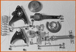
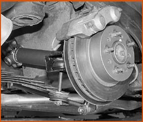
In this two-part series, you'll see how to remove and replace the hard working parts which hold the rubber to the road.
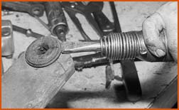
Begin by disconnecting the outer end of the spring. Remove the cotter pin, hold the bolt with a strong 13/16 open end wrench (box wrench, if it will fit) and break the nut loose with a 7/8 box wrench or socket. Tip: spray these nuts (and the other suspension fasteners) with penetrating oil a few days beforehand. If the road spray has really rusted the threads, it may be necessary to heat one flat on the nut with a torch.
After the nut is broken loose, position the jack as close to the outer end of the spring as possible. Jack up slowly until the tension is off the spring bolt. Tip: fasten a C-clamp or Vise Grip on the spring just inboard of the jack (or post) to prevent the jack from being thrown off as the spring is lowered. This is less of a problem with fiberglass springs and heavy duty springs because they have less of an arch. Remove the nut, washer and cushion and then slowly let the spring down.
Tip: Pick up the rear end of the T-arm and insert a small socket under the arm against the frame. This will hold the arm closer to its normal riding height, and will make work on the strut rod and axle shafts easier because they won't be on such an angle. Remember this later when it's time to reinstall the shock mount through the strut rod.
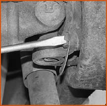
Use a 3/4 wrench or socket to remove the lower shock nut. Remove the lock washer and then the cupped washer (it may have to be turned off). Gently pry the lower end of the shock off, and be careful not to dent it.
After the shock is disconnected, remove the cotter pin and castellated nut (15/16 socket) from the shock mount. Resist the temptation to tap on the end of the shock mount. Even if the nut is reinstalled backwards for added protection, hammering will mushroom the end and ruin this expensive part.
Install a shock mount remover tool and hammer the part out. The shock mounts are usually quite rust-seized inside the steel strut rod bushing sleeve, and the cost of the tool is many times cheaper than replacing these parts.
 Use
a screwdriver and hammer to tap the tabs of the French lock away from the axle
flange bolt heads. Tip: tap a six-sided 5/8 socket firmly onto the bolt before
attempting to break it loose. You don't want to round the head over. If
replacement bolts and lock washers have been substituted, I recommend getting
the original French locks and grade 8 shoulder bolts before reassembly. Later
models used smaller bolts without French locks.
Use
a screwdriver and hammer to tap the tabs of the French lock away from the axle
flange bolt heads. Tip: tap a six-sided 5/8 socket firmly onto the bolt before
attempting to break it loose. You don't want to round the head over. If
replacement bolts and lock washers have been substituted, I recommend getting
the original French locks and grade 8 shoulder bolts before reassembly. Later
models used smaller bolts without French locks.
If an impact wrench is used to remove these bolts, break the bolts loose first or their heads may round over. To prevent the axle from turning while loosening (or tightening) bolts, lock the rotor against the caliper. Using a 3/8 drive extension against the caliper housing is better than using a screwdriver against the pad pin, but either will work.
If you want to replace the U-joints, now is an excellent time. If you are lucky, your differential yokes will have caps which can be removed relatively easily with a 9/16 socket. Earlier (and standard) differentials have U-bolts which can be tedious to remove, and they often rust-seize inside the yoke.
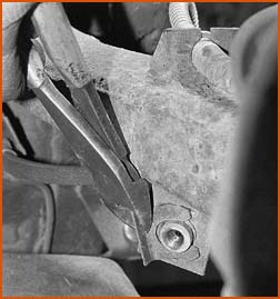
Two long 3/4 box wrenches can help break loose the camber nut on the inner end of the strut rod. Hold the bolt head with one wrench and turn the nut off. Note the strut rods were bent by someone in an attempt to set camber. Although unfortunately common, this is not a wise practice because bending weakens the ability of these rods to take compression loading.
Tap the camber bolts out. Watch for two reducing washers to fall from inside the strut rod bracket. It is easy for them to roll away and get lost, but they're one reason why the camber bolt won't rust-seize inside the inner bushing. Gently pry the rod out after the bolt is removed.
Use a 5/8 socket to remove the two rear caliper mounting bolts. The brake line may have to be bent slightly to permit access to them. Tip: Whenever breaking bolts loose during suspension work, it's a good idea to wear gloves to prevent gashes on your hands if the tool slips.
Disconnect the brake line at the hose and remove the hose clip. If the T-arm is not being removed, the line does not have to be disconnected here; slide the line through the bracket and tie the caliper up to the frame.
Remove the cotter pin from the trailing arm bushing bolt, then remove the nut, lock washer and flat washer. Take note that this flat washer is a little thicker than standard. Also, be aware that Corvette's rear wheel bearing assembly can be removed without removing the T-arm.
Tap the bushing bolt through the T-arm. If a lot of force is needed, apply duct tape or use other means to protect the paint on the lip of the fender. We were fortunate there was very little rust on the suspension parts and they all came out easily. However, if this bolt is rust-seized inside the bushing, it may have to be cut by a saw or torch to enable T-arm removal.
 Remove the cotter pin, the spindle nut, its flat washer and the spindle flange.
Use a 1-1/16 inch socket on the nut. The flange usually slides off relatively
easily because the wheel bearing grease has kept its splines from rusting.
Remove the cotter pin, the spindle nut, its flat washer and the spindle flange.
Use a 1-1/16 inch socket on the nut. The flange usually slides off relatively
easily because the wheel bearing grease has kept its splines from rusting.
After removing the rotor, insert a screwdriver in by the top of the shoes and pry one end of the retaining spring out of its hole. You can rotate the spindle and look in through the large adjusting hole to better see the end of the spring.
Pry the shoe out from behind the spindle, grasp the retaining clip with needle nose pliers, push in and turn the clip to free it from its pin. You can put your finger in from behind the front pin to hold it in place while doing this, but the rear pin can't be reached from behind. If necessary, hold it from the front with a second pair of pliers.
Remove the 4 nuts which hold the bearing assembly to the T-arm. A long 9/16 box wrench works best to break them loose if the spindle assembly is being removed from the T-arm. If the exposed threads of the studs are rusty, wire brush them and then use penetrating oil to make removal of the nuts easier. You don't want to break the other end of the studs loose.
The bearing assembly is not press-fitted into the T-arm, but rust usually makes a little persuasion necessary for removal. If the spindle has been removed, remove the caliper mounting bracket before attempting to remove the bearing support. However, if removing the spindle assembly, tap the lower end of the bearing support forward and then backward (as far as the studs will allow) to help break it loose. Only tap on the reinforced (webbed) area of the support.
The easiest way to remove the T-arm bushing is to saw the bevel washer in half, remove it, and then cut off the flared end of the bushing sleeve.
 After pressing or tapping the sleeve out, each half of the bushing can be popped
out of the T-arm. The T-arm should be measured for straightness and checked for
rust damage before it is refinished and rebushed. In this case, the T-arms were
in excellent condition and did not have the tell-tale bulges or split welds
which occur when rust forms between the overlapping metal sections. After
disassembly and degreasing, the parts were blasted to remove all old paint and
surface rust. Epoxy paint was then applied to duplicate the appearance of the
original finish.
After pressing or tapping the sleeve out, each half of the bushing can be popped
out of the T-arm. The T-arm should be measured for straightness and checked for
rust damage before it is refinished and rebushed. In this case, the T-arms were
in excellent condition and did not have the tell-tale bulges or split welds
which occur when rust forms between the overlapping metal sections. After
disassembly and degreasing, the parts were blasted to remove all old paint and
surface rust. Epoxy paint was then applied to duplicate the appearance of the
original finish.
Installation of the T-arm bushing requires a tool which compresses the bushing while one end of the bushing sleeve is swedged over to hold the bushing assembly together.
The bearings in Corvette rear wheels are just two fairly large tapered roller bearings, but rebuilding is much more involved than simple replacement. Many Corvette repairers and owners have found this out the hard way. The safest and easiest choice is to send them to Van Steel for a precision rebuilding. Factory specifications for axial clearance are up to eight thousandths of an inch. Van Steel sets each assembly to within one thousandth of an inch. That's one of the reasons why they've never had one wear out yet.
When the bearing assembly is rebuilt, one parking brake hold-down pin and the backing plate (rotor dust shield) it goes through are "trapped" between the spindle and the bearing support. If those parts are to be replaced, that is the time to do it. Options to consider are an original cadmium plated shield or a stainless steel pin. Don't neglect to inspect and recondition the spindle flange. Cleaning the threads is obvious, but be aware that the seal surface, its edge, and overall length are critical, too. The inner surface often gets damaged during bearing failures.
Lightly coat the seal surface with grease before installing it. Install the large flat washer and tighten the spindle nut to 100 lb-ft. After installing the cotter pin, trim it close to the nut to prevent interference when the axle flange is bolted on.
After the bearing assembly is rebuilt, it is custom fitted with a rotor which will reduce the runout (wobble) to well below factory specifications. After fitting, the rotor should be kept on the same side and in the same alignment to the spindle. If you have good rear calipers but air has been getting into the system, excessive rear rotor runout is the likely culprit.
Check to make sure all the parts are on their correct sides. The round shock mount hole in the bearing support goes toward the front of the car, and the parking brake levers go toward the rear.
Wheel bearing replacement provides a convenient opportunity to replace the axle shaft U-joints. These are available as exchange, or you can have yours rebuilt at the same time as the bearings. However, non-grease fitting U-joints are original and are recommended for high horsepower motors.
Don't forget to hold the two "trapped" reducing washers onto the strut rod while inserting it into the bracket. The camber bolt then goes in from the front, with the nut toward the rear of the car.
Position the T-arm at close to its normal riding height before tightening the nut on the T-arm bolt. This position also helps for the insertion of the shock mount.
 Install the caliper, and connect the rear spring. Check all the nuts and bolts
one more time before putting the car on the pavement, and then take a road test
with tight corners at low speeds as a final check. Camber and toe-in will have
to be reset, but in this case we'll wait because the front suspension is now
being rebuilt. And that's the subject of the second half of this suspension
rebuild series.
Install the caliper, and connect the rear spring. Check all the nuts and bolts
one more time before putting the car on the pavement, and then take a road test
with tight corners at low speeds as a final check. Camber and toe-in will have
to be reset, but in this case we'll wait because the front suspension is now
being rebuilt. And that's the subject of the second half of this suspension
rebuild series.

For a complete version of this story in print, look for Corvette Fever on your local newsstand.


Copyright(c) 1997: Dobbs Publishing Group.